目录
序言
原题复现
我的设计
序言
上篇博文:
HDLBits 系列(30)Serial Receiver
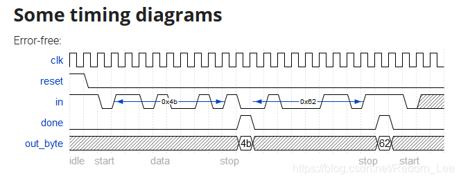
写了串行接收器如何接收8位串行数据,正确接收8位串行数据后给一个接收完毕标志信号,这篇博文来继续进一步输出正确接收的串行数据,在done有效时刻输出并行的8bit数据。
特别容易实现,对上篇博客的代码进行略微添加即可。需要注意的是这种uart协议先发送的bit位为低bit位。
原题复现
先给出原题,在给出设计:
Now that you have a finite state machine that can identify when bytes are correctly received in a serial bitstream, add a datapath that will output the correctly-received data byte. out_byte needs to be valid when done is 1, and is don't-care otherwise.
Note that the serial protocol sends the least significant bit first.

我的设计
设计如下:
module top_module(input clk,input in,input reset,    // Synchronous resetoutput [7:0] out_byte,output done
); //// Use FSM from Fsm_seriallocalparam START = 0, B1 = 1, B2 = 2, B3 = 3, B4 = 4, B5 = 5, B6 = 6, B7 = 7, B8 = 8, STOP = 9, DONE0 = 10, DONE1 = 11;reg [3:0] state, next_state;always@(*) begincase(state)START: beginif(in == 0) next_state = B1;else next_state = START;endB1: beginnext_state = B2;endB2: beginnext_state = B3;endB3: beginnext_state = B4;endB4: beginnext_state = B5;endB5: beginnext_state = B6;endB6: beginnext_state = B7;endB7: beginnext_state = B8;endB8: beginnext_state = STOP;endSTOP: beginif(in == 0) next_state = DONE1;else next_state = DONE0;endDONE0: beginif(in == 1) next_state = START;else next_state = B1;endDONE1: beginif(in == 0) next_state = DONE1;else next_state = START;enddefault: beginnext_state = START;endendcaseendalways@(posedge clk) beginif(reset) state <= START;else state <= next_state;endassign done = (state == DONE0) ? 1 : 0;// New: Datapath to latch input bits.reg [7:0] out_byte_mid;always@(*) begincase(state)START: begin;endB1: beginout_byte_mid[0] = in;endB2: beginout_byte_mid[1] = in;endB3: beginout_byte_mid[2] = in;endB4: beginout_byte_mid[3] = in;endB5: beginout_byte_mid[4] = in;endB6: beginout_byte_mid[5] = in;endB7: beginout_byte_mid[6] = in;endB8: beginout_byte_mid[7] = in;endSTOP: begin;endDONE0: begin;endDONE1: begin;enddefault: begin;endendcaseendassign out_byte = (done == 1)? out_byte_mid:'bz;endmodule
测试成功。